Motion Control and System Engineering Considerations

Interesting Projects Blog
September 22 2024 | Donald P. Labriola PE
Motion Control choices are best be made in light of the whole system architecture, as the selection of system architecture will drive not only the implementation and integration stages of the project, but also manufacturing and field service, and even the ability to ship and install the final product. We will first review a quick tour of System Engineering, and then go on to the Motion Control specifics.
SYSTEM ENGINEERING
The essence of System Engineering is taming the explosion of the desired and accidental interfaces in the system, thus preventing or at least reducing undesired modes of interaction. This process is done by thoughtful system partitioning, with the careful choice of interfaces, and an eye to robustness, testability, and margins. Unwanted interactions often lurk in shared resources. Thus, it is advised to minimize the sharing of resources where possible, and where sharing is needed, use careful planning and analysis of requirements and margins. Self-monitoring of critical parameters within the shared resource can be used to verify these target design margins. Examples include providing separate processors for separate subsystems to avoid shared resources and the use of runtime pressure monitors within a pneumatic system to verify actual margins while in operation.
The sharing of low-level power supplies across diverse systems can also result in unexpected interactions in which each subsystem separately tested shows no problems, but the combination intermittently fails. This very issue forced the return of a large fielded instrument to the factory for investigation. The problem was intermittent noise on an analog channel caused by a crushed catch diode mounted on a solenoid in a different section of the instrument. The cause was too far removed from and indirectly coupled to the “victim” electronics to be located by field service personnel – even after replacing virtually every PCB and harness in the system. The accidental interface in this instance was a shared 12v supply.
PARTITIONING THE SYSTEM
The key step in the System Engineering process involves partitioning of the system. Partitioning not only selects the types and number of interfaces, but also determines how the system is designed, debugged, integrated, manufactured, and serviced in the field. Standalone subsystems containing the mechanical, electronic, and software components needed to operate that subsystem are most easily developed in parallel, tested in manufacturing, and reused in later projects.
Physical packaging requirements – including shipping and installation – drive system partitioning and must be addressed from the very start of a design. The ability to bring completed sections of the system through a 29 inch doorway at the customer’s premises, to fit sections into small elevators (three foot sections as a rule) and the ability to package systems for safe shipping a standard 747 cargo container. Failure to consider packaging requirements early in the design has caused major redesign late in the process of more than one project. Ideally, the number of interfaces that cross the physical separation boundaries should be minimized to reduce packaging time and installation reassembly time and complexity at the customer site. Physically locating control electronics in close proximity to the mechanical systems they control makes this type of physical division easy, whereas the use of a centralized control system can make for many cables that must be disconnected before shipping and then rerouted and reconnected to their proper locations at install time.
INTENTIONAL AND UNINTENTIONAL INTERFACES
Intentional interfaces include power, communications, and mechanical system alignment methodology. Unintentional interfaces can include power-system noise interaction, ground loops, and mechanical structure deflection, where the motion of one axis to compromises the operations of another axis. Shared communications channels can cause a system timing to change in one subsystem to cause changes in timing in another subsystem sharing the channel. Standard Ethernet may work acceptably with low loading and then randomly show large delays as the loading increases even slightly.
Shared processor resources may also have a very similar effect if adequate care is not given to prioritization and worst-case analysis considering all systems – in both normal and fault recovery modes. These timing effects become more pronounced if finer grained, hard real-time coordination tasks are moved to higher levels of the system. This caused by having more items in the critical path.
DRAWING THE DIVIDING LINES
The criteria for selecting the dividing lines within the system are: 1) minimize the number of interfaces, 2) with the intentional interfaces being well defined, understood, and testable with understood margins, and 3) a suppression of inadvertent interfaces both as they are affected by other systems (victims) and as they affect other systems (aggressors). To the ability of the system team, the unintentional interfaces must be located and either eliminated or converted to intentional interfaces with testable margins. Unintentional interfaces are the most common root cause of integration problems when attempting to combine otherwise functional subsystems.
To meet these criteria, the subsystem boundaries need to be consistent for the electronic, mechanical, and software teams. Such common boundaries help enable interdisciplinary teams to work to the same goals. Critical system resources shared between different subsystems often leads to problems at integration time as the reality of the number of accidental interfaces within these shared resources are painfully learned. Sharing processors between multiple subsystems with hard-real-time requirements can reveal subsystems that work well individually but may become erratic or non-function at all when integrated. Unintended interfaces in software include priorities and latencies where fixing or modifying one subsystem can break another subsystem. This leads to the need for much deeper regression testing following even a minor change as all of the subsections sharing the resource need to be verified.
CONNECTING THE PARTS TOGETHER
Use common and well-defined media and protocols within the system. Select robust interfaces: for example, RS-485 supports higher speeds and longer runs than RS-232, RS-485 also tolerates larger signal ground shifts. CAN is also differential with similar benefits, and has controlled latency and deterministic priority along with support for small packets and built in error detection. Ethernet is both fast and isolated, but special protocols and hardware may be needed to implement fast signaling with guaranteed low latency.
When designing Mechanical interfaces, consider using six-degree-of-freedom mounts, also called kinematic mounts. When combined with software alignment, this approach can simplify assembly and maintenance, allowing a part to be removed and remounted without realignment. The resulting mechanical interface is more robust, clearly defined, and testable with the tolerance analysis done earlier in the design process.
MOTION CONTROL
Motors are a common electronic to mechanical interface, while their controllers are involved in the software to electronic interface. Their selection depends on many issues including life expectancy, tolerance over their expected life, contamination requirements, heat considerations, allowable noise levels, safety requirements, motion requirements, and the variability of the load. DC brush motors are very cost effective and are available with a wide range of speed and torque capabilities, but they can generate EMI from the arcing at the brushes and produce contaminating dust from the wearing of their brushes. They also have relatively short life expectancies.
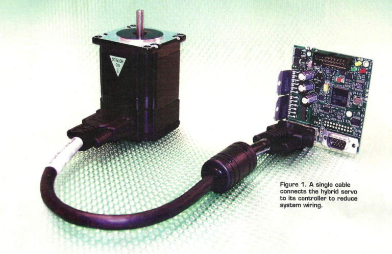
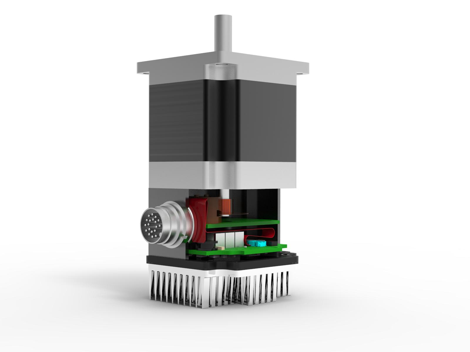
Many systems have requirements that will preclude the use of DC brush motors in some or all axes. Brushless motors overcome these problems and may be operated either commutated or non-commutated. Operated in non-commutated mode, brushless motors include Stepper motors, synchronous motors, and induction motors. These same styles of motors when operated with feedback and commutating controllers/drivers become servos in position or variable speed applications. Commutated brushless motors include both two and three phase brushless configurations. High pole count motors – called stepper motors when operated open loop – become Hybrid Servos when commutated and operated in closed loop operation. The Hero image Figure 1 shows an example hybrid servo.
The selection of Motors used in positioning applications, such as the cranes or pumps seen in many medical applications, usually come down open loop steppers, or closed loop DC or brushless servos. DC brush motors must be properly encased to eliminate the contamination from the wear of their brushes, and their life expectancy typically ranges from tens of hours to a few thousand hours of operation without maintenance. Open loop stepper motors are relatively inexpensive, and many are designed for long life, but they may generate enough heat to significantly increase sample evaporation or cause other thermal issues within the system. Stepper motors can also be acoustically loud and cause mechanical vibrations in the system, according to how they are driven, and they may lose position due to strong resonances as well as to varying load conditions. Stepper motors do have a very high torque constant, allowing for direct drive or low gear/pulley ratios for many loads.
Closed loop brushless in general have higher performance and higher cost. The number of pole pairs of the motor trade speed for torque, with more speed for a lower number of poles and more torque for higher number of poles. Stepper motors and other high pole count motors can be paired with feedback and commutating drives to operate as high pole count servo motors, the combination referred to as “hybrid servo motors” or “direct drive motors” by the various vendors. Proper commutation and closed loop control of these motors eliminates the low and mid frequency resonances and minimizes the power usage while greatly improving their performance, reducing acoustic noise while eliminating lost steps.
Many applications have loads with higher torque requirements, from friction, load, or inertia components. The torque requirements may be met by a combination of belts and pulleys or gears. Lower torque motors require higher gear ratios, while higher torque motors may be able to direct drive their loads, or may be able to drive with a single pulley/belt or gear stage. Single pulley/belt systems can handle up to about 7:1 or 8:1 ratios with low cost, good damping, and quiet operation, often with a substantial cost reduction. Pulley systems (with appropriate materials) can provide long life with little chance of the type of contamination that follows seal failure on a gear head.
Motion systems with low ratio drives or direct drive operation have a better survival rate, in general, for manual back driving, that occurs when an operator manually clears jams in a system. Many high ratio gear trains needed to provide high torque output from a fast, low torque motors can be easily damaged when manually back driven, causing either immediate or worse, slightly delayed failures or intermittent operation.
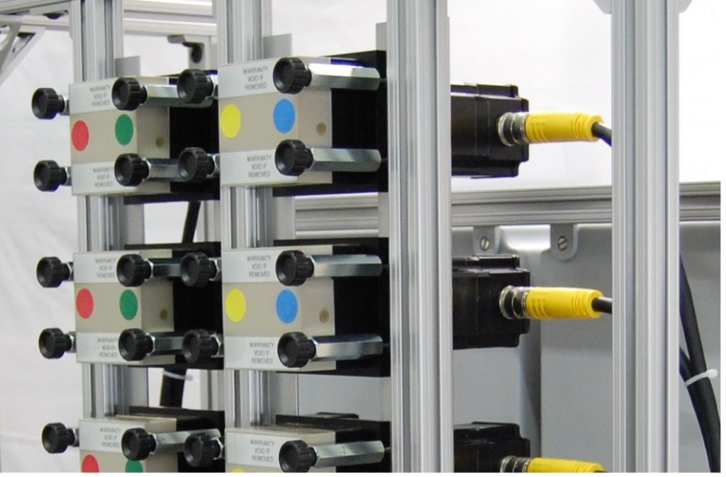
Figure 2 shows a portion of a bank of 10 positive displacement pumps used to package contact lenses. These pumps take advantage of the capabilities of direct-drive hybrid servo operation in a high stiction environment. John Beard, president of Car-May (www.Car-May.com) is quoted saying, “with flow rates between – one microliter per hour to 300 milliliters per minute, the turndown ratio is 18,000,000. This is only possible because of the direct drive.”

Lead screw based pumps and linear actuators generally have a critical speed rating in the range of 500 RPM to 2000 RPM , which allows direct driving with a hybrid servo while utilizing its optimal performance range . Direct drive operation saves the cost and maintenance of adding gear-heads, while reducing size and weight. Direct drive operation with high torque hybrid servomotors can be effective in de-capping as well as recapping sample tubes, as the torque is easier to measure at the motor without the added effects of a gear-head. Direct drive systems eliminate gear backlash and wear, and typically function better in high stiction environments such as pumps with sliding seals. Lack of overshoot, backlash, and ringing on pumps can be especially important to produce repeatable results.
Consider the System Engineering approach to design as a means to divide and conquer a complex system. Proper partitioning and robust interfaces can greatly simplify subsystem testing and system integration at the design stage, in production, and in the field. Proper selection of motor types as well as controllers can significantly speed the design and optimize the final product.
Related Posts

Operational Advantages of Integrated Motors
Operational Advantages of Integrated Motors Interesting Projects Blog April 17 2024 | Donald P. Labriola PE Combining a motor with

Integrated Hybrid Servo Motors Vs Standard Integrated Servo Motors
Integrated Hybrid Servo Motors Vs Standard Integrated Servo Motors Interesting Projects Blog April 10 2025 | Donald P. Labriola PE
