Improperly Testing Belt Tension Can Easily Damage Small Motors

Interesting Projects Blog
July18 2024 | Donald P. Labriola PE
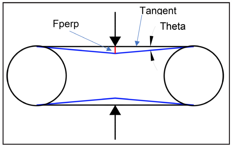
Most of us want to just instinctively squeeze a belt between a pair of pulleys to test the belt tension. What is not as instinctive is just how much force such a procedure can put on the shaft — often significantly past the manufacturer’s rated limits for small motors. This can cause damage to both the shaft and the bearings. First a diagram (Fig. 1) and a little math. The force calculations are not dependent on the diameter or spacing of the pulleys, but let’s assume the pulleys at a spacing of 4 inches (100 mm) for other parts of the discussion where we calculate deflection.

For a 5-pound squeeze (22N) and a 5 degree angle (0.139 radians), the tangent is 0.132. (or approximately the angle in radians, if you still remember your old-math, small-angle approximations). This says the tangent force from each side is 7.6Å~ larger than the applied squeeze, and both sides contribute to the pull on the shaft; so both shafts see 15.2Å~ the squeeze (half of which is counteracted by the belt to the left and half to the right) — or about 38 pounds” (170 N) of compression. The 5 degrees deflection corresponds to approximately 0.26 inch (6.6 mm) of deflection on each side.
But you say I would not squeeze that hard, more like one pound (4.4 N). So, let’s linearize and estimate that the deflection would be about 1⁄5; so the angle would be only 1 degree. The deflection of each belt would then be about .05″ (1.3 mm) — that should not be so bad.
Well, the deflection is now .0262 radians, and Tan (.0262) = .0262 (to 3 significant places), so the force multiplier is now 1⁄.0262 or 38.2Å~. When accounting for both sides of the belt, this is now a multiplier of 38. The unexpected result is that with this lighter force and the smaller deflection, it is still putting almost the same enormous force between the two shafts!
While there was an assumption of linearity of deflection to simplify the calculations — and this is not a perfect assumption and the width of the force application is also not infinitesimally small — but this order of magnitude calculation (given the force and the deflection) is still fairly close. This should cause one to pause to think before you pinch! — especially if you are working with small motors having . inch or smaller shaft diameters. A typical NEMA 17-frame motor specifies no more than 6.2 lbs at .78 inches (28 N 20 mm) from the flange, while a NEMA 23 calls out 17 pounds” at .78 inches (75 N 20 mm) from mounting flange. In both of these cases, the 38 pounds” (170 N) would be well in excess of the motor ratings, bending shafts and or damaging bearings.
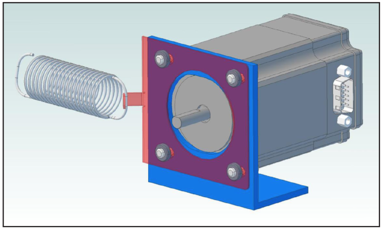
A much better way to actually set a calibrated belt tension is to provide a metal “sled” holding the motor to which you can attach a fish scale or a known hanging weight (around a pulley if you want a side force). Set the tension, tighten the screws; belt tension is now set to a known and repeatable level. This gives your servo systems more repeatable servo tuning, while not accidentally damaging shafts or bearings. An example drawing of such a motor “sled” is shown at www.quicksilvercontrols.com/SP/TD/QCI-TD076_Belt_Tightening.pdf
QuickSilver Controls produces compact, high-performance integrated servo motors and controllers and provides assistance in applying them to customer systems. Disclaimer: As usual with free advice, do not depend on these calculations for your critical designs. Perform these calculations yourselves and/or make the appropriate measurements. The author takes no responsibility for any errors or omissions. The information is only provided for your entertainment and insight into possible issues.
Related Posts

Operational Advantages of Integrated Motors
Operational Advantages of Integrated Motors Interesting Projects Blog April 17 2024 | Donald P. Labriola PE Combining a motor with

Integrated Hybrid Servo Motors Vs Standard Integrated Servo Motors
Integrated Hybrid Servo Motors Vs Standard Integrated Servo Motors Interesting Projects Blog April 10 2025 | Donald P. Labriola PE
