DUAL LOOP MOTION CONTROL WITH ONLY ONE ENCODER
Interesting Projects Blog
August 1 2024 | Donald P. Labriola PE
Dual loop control is often used to improve the performance of a motion control system. Although this appears more complex at first look, the overall system cost and complexity needed to reach the desired level of precision may often be significantly reduced. In the example system, mechanical stiffness was improved by a factor of approximately 100 by the use of a secondary feedback device.
In the case of a single loop lead screw system, the feedback is usually located on the back of the motor. Each element in the system between the sensor and the load adds to the uncertainty. The motor mounted feedback is blind to torsion of the shaft with load. The coupler between the motor and the lead screw distorts under load, causing error between the motor shaft and the lead screw. The lead screw itself can also exhibit torsion under load, varying with both load and position of the nut with respect to the driven end of the screw. The lead screw itself typically has periodic error which can be very expensive to minimize, and the nut backlash minimization can add load as well as wear to the system. Finally, the thrust bearings’ accuracy also directly affect the system. The result is a system in which many elements can degrade the performance, and tightening the system can be expensive. As the feedback only senses the back shaft of the motor, much of what happens after that is unknown to the control system and thus not able to be corrected.
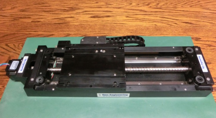
Adding a second feedback sensor (the optical track shown in insert) that measures close to the end effector of the system can significantly improve the performance while reducing the cost. Looking at the above system again, most of the error contribution is inside the secondary control loop; this error can be measured and thus corrected. With a good gain margin, the system error can be brought down nearly to error of the secondary feedback sensor. Rolled lead screws can replace ground lead screws, with their thread pitch variation, both cumulative and periodic, compensated for by the use of the additional feedback sensor. Differential thermal expansion coefficients of various elements may also be compensated.
For effective dual loop stiffness, a good system bandwidth is still needed. Elements of the system should be selected to minimize lost motion. The tighter system reduces the corrective action required of the control system just to hold a stationary position. Other periodic errors, such as lead screw pitch variation and thermal effects do not affect system stability and are well tolerated, but if significant, may require more control effort. The contribution of the errors within the loop are typically reduced by approximately the gain of the system, so a high gain system is desired.
The velocity feedback provides the phase stability for the system, as the position feedback is more than 180 degrees behind the phase of the supplied torque (180 degrees is the most optimistic). This velocity feedback is typically taken from as close to the motor to allow sensing and control of the energy being put into the system while lost motion or backlash is being corrected.
The IBEX lead screw system tested uses a 0.1 micron secondary feedback, direct driven by a QuickSilver hybrid servo with integral resolver – Mosolver – to provide 32,000 count resolution at the motor, corresponding to .25 micron per count. The closed loop system holds position within +/- 2 counts when adding a 20 Newton (5lb) load. The motor corrects the compliance in the system under this load by moving approximately +/-225 counts (2.5 degrees) when the load is applied. With the same system operating single loop, the motor will hold steady within +/-2 counts as a 20 Newton (5 pound) load is applied in either direction, while the linear scale shows a movement of approximately +/- 120 counts (12 microns). Thus a properly implemented dual loop system excels not only in compensating lead screw tolerances, but also in significantly stiffening the resulting system under load.
* The second sensor for the motor is built into the Mosolver.
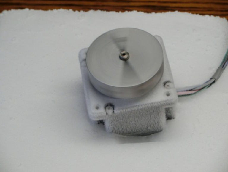
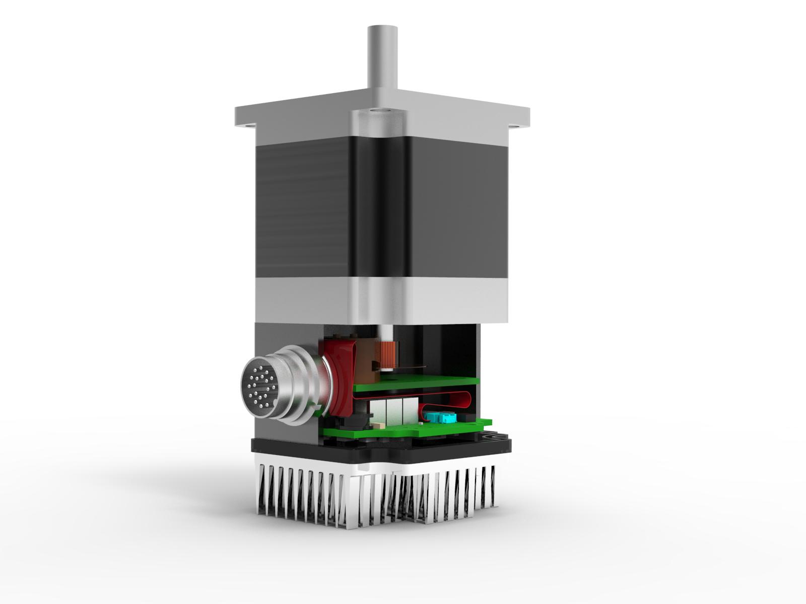
Motor with Integral Resolver (Mosolver)
Resolvers determine position by operating as a variable transformer between the excitation coils and the sensing coils. The coupling varies, typically sinusoidally, as the rotor component is rotated. The excitation in a typical resolver is either brought in via brushes to a coil within the rotor, with the sensors on the stator, or via a separate excitation stator is coupled to rotary transformer on a portion of the rotor which then excites the rotor windings opposite to the stator sense windings. This configuration requires multiple rotor and stator components for sensing position, all of which need to be added to the motor itself. In addition to the added components, volume, and weight, a separate sensor excitation drive must be provided, and some degree of magnetic isolation is needed to prevent the motor PWM noise from getting into the resolver sensing circuits. With typical single coil excitation, dual coil sensing, the excitation sine wave passes through zero volts twice per drive cycle, causing periods over which the resolver is “blind” and must use filtering techniques to provide a best estimate of what the motor is doing while the resolver is in this excitation zero crossing region. These techniques can give rise to delay and loss of phase margin within the system.
The resolver within the motor overcomes many of these obstacles by re-using the motor magnetic paths and PWM drive to provide excitation to the position sensing coils. The motor ripple current, which results from the PWM drive, causes a time varying flux component with a high frequency component. The degree of overlap between the rotor and stator teeth modulates the effective reluctance of the paths through different sets of stator teeth. The ripple flux is thus directed variably to different sections of the sensor coil, resulting in approximately sine and cosine signals when the sensed voltages are properly sampled in synchronism with the motor PWM drive. As the sine and cosine signals are updated every PWM cycle, the delay is minimal and does not degrade system phase margin.
The electrical cycle of the sensor matches that of the motor. With the sensor built on the same magnetics as the motor, the signal is automatically aligned and is used for commutation without needing phasing adjustments. When using a high-pole count Hybrid Servo motor shown, there are 50 electrical cycles per revolution. With 640 positions per cycle, the resulting resolution is 32,000 counts per revolution.
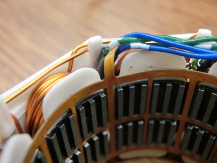
The sensor consists of a robust polyamide flex circuit holding the sense coils which is added to the stator of the motor. The sensor can be made to exceed the temperature and other environmental capabilities of the motor, the resulting system having the full environment rating of the motor itself, with a footprint that matches that of the motor.

Related Posts
Operational Advantages of Integrated Motors
Operational Advantages of Integrated Motors Interesting Projects Blog April 17 2024 | Donald P. Labriola PE Combining a motor with

Integrated Hybrid Servo Motors Vs Standard Integrated Servo Motors
Integrated Hybrid Servo Motors Vs Standard Integrated Servo Motors Interesting Projects Blog April 10 2025 | Donald P. Labriola PE
Interesting article, gave me a lot of inspiration.