Interesting Projects Blog

April 8 2024 | Donald P. Labriola PE

A ferrite core is commonly placed over a cable in an attempt to reduce noise, both radiated and as it interacts internal to the system, and to reduce the received noise. The ferrite forms a common mode coupled inductor / transformer for each of the signals passing through it. The range of frequencies of the is coupling dependent upon the type of material used in the bead, how many turns are wound, and how the turns are physically wound. The inductance also depends on the physical geometry of the ferrite material.

First, we will begin with the basic textbook equations for the inductance of a wire passing through a core. The inductance can be calculated as:


To change this to word problem format:  the inductance goes up with the square of the number of turns, with the permeability of the core and with the cross section of the core. Inductance goes down with the mean path length (average circumference of the path around the wires). 

Using the same material, a thick bead (large area) with a small internal hole (smaller radius r) has a significantly higher inductance than a thin ring (small area) with a large hole (large r). A few turns can significantly increase the impedance if they can fit through the core. Winding is important to prevent capacitive coupling between the turns from “bypassing” the bead impedance. In general, use the bead with the smallest hole available that will fit the cable.

Reality adjustment: Many of the ferrite beads commonly used for filtering have large resistive losses and are not simple inductors. However, this is often a good thing as lossy ferrites convert the electrical noise issues into heat; as long as the heating is not excessive, this keeps the noise from just being conducted or radiated elsewhere. A even worse effect is when the noise is resonated, which can significantly increase the effects of the noise. (Note that resonance is used intentionally when trying to radiate RF energy in a radio transmitter!)There are many different ferrite “recipes” or blends available, targeted for many diverse purposes. The blends used for a high efficiency switching power supply often would not be the best for use in filtering power cables, for example. According to the frequency of the switcher the materials and often their processing will also commonly vary. Higher permeability materials allow for significant impedances at lower frequencies but are also more easily saturated – that is their permeability drops rapidly as the net current through the aperture of the bead increases. 

A simple fix that allows the use of these higher permeability cores while avoiding the saturation is to form common mode inductors where the sum of the currents through the wires are fairly well balanced as only the net current through the core gives rise to the magnetic field in the core. The coupled inductor that results from passing sets of signals through a ferrite bead can be used in multiple ways to reduce noise issues.

The first example using the bead as a BALUN – a contraction of Balanced-Unbalanced. A Balun configuration can be used to convert balanced signal lines into a unbalanced line or vis versa.

A good example of an unbalanced signals would be the drivers powering a motor: these are usually switched one-at-a-time rather than differentially (as would be the case for a RS-485 line).

We will draw this for a 2 wire system, but the same concept applies to a 3 phase system. The schematic shows the phase that is not switching as being grounded, while the phase that is switching at this time is shown as a pair of transistors. Not shown is the capacitance between the wires nor from the wires to the surrounding environment.

When the signal at IN1 takes a step, and we will describe for the positive transition here the step in voltage a the transistor causes a current to flow into IN1 wire that is needed to charge the capacitances associated with IN1. This current causes a positive to negative voltage drop from IN1 to Out1 due to the rapid change in current interacting with the inductance of the ferrite bead. This reduces the size of the step at OUT1 as compared to the step size at IN1. This same negative voltage step (from the transformer function of the bead) appears OUT2. If the step is sufficiently fast compared to the bead inductance, the output will be (instantaneously) nearly balanced. That is, OUT1 will step to half of V++ while OUT2 will go to minus one half of V++. The voltage between the two conductors at the input will also be essentially the voltage between the two conductors at the output. However, at the input the average of the two wires jumped to one half the supply voltage, while at the output the average remained almost at zero volts (for the high frequency components of the waveform). This greatly reduces the coupling to nearby signals. The current is also forced to be essentially equal (at high frequencies) reducing the net H-field from the wires. I earlier noted that this was true for an instant, but over time, the rate of change of the current will decrease, causing the voltage drop across the bead to decrease, and eventually OUT1 will reach V++ and OUT2 will return to zero. The frequency at which this happens can be made significantly lower than the switching edge frequency, which significantly reduces the emissions.The use of a twisted pair (or triple) causes the polarity of the coupling from each wire to reverse at the wire twist rate, which (for balanced lines) reduces both e-field and h-field coupling to the adjacent wires to mostly cancel out. This can be improved further both by the use of shielding (For the electric fields), and by using a different twist (turns per length) for the encoder versus the motor signals in a cable so that the magnetic loops of the two sets of conductors do not align. Both the shielding and the different twist counts are used in CAT-7 to reduce coupling between pairs.

But how about the Shield?

A shield is often added around the driven wires between the driver and the motor to reduce the electric field from the drive wires from radiating. The question always comes up as to where and how to ground the power cable shield. 

We have found that grounding the shield – either directly or through a significant capacitor – at the drive, and also grounding the driver signals shield at the motor significantly reduces the radiated noise from the drive. Note that the power supply is often not directly connected to the chassis ground, but generally EMI filters add a capacitance from the DC rails to the chassis. This is not shown for simplification, but the return paths for high frequency signals are still present.

The first thought is that this configuration is forming a ground loop through the chassis as the driver and the motor are  both connected to the chassis, and thus it should be avoided! For feedback signals that do not inject (significant) current into the chassis, this is certainly the case – ground one end of the shield. For the motor, the extra capacitance between the motor and the stator changes this. A ferrite bead over the whole cable also changes the operation.

Lets first look at what would happen if the shield connection to the motor were not present. A positive step at IN1 will cause OUT 1 to go positive and OUT2 to go negative, but the extra capacitance of the shield will give an additional current path through the ferrite bead and it will not work as nicely balanced as the balun example above. The motor windings have a capacitance between them and the stator of the motor. The step in the average voltage to the winding will induce a current through this capacitance into chassis ground when the driver takes a step. The only return path for this current is through the chassis, and so there will be a loop through the cable to the motor and back through the chassis. The noise will be radiated by the cable and through the chassis ground.

Now lets see what happens if the chassis IS connected at both the driver and to the motor. The ferrite will “attempt” to minimize the net change in current through the bead. In this example, a 100 ohm bead is used (100 ohms at 10MHz). The current from the step on IN1 will cause a small negative voltage on the output side of the shield conductor, such that most of the current capacitively coupled to the motor stator will be drawn back through the shield. 

To greatly simplify: current that passes in one direction has to pay the 100 ohm toll (bead impedance) to flow, while that current which returns back though the bead does not pay the 100 ohm toll as the magnetic fields produced by the two wires will cancel. This makes the return path through the shield going through the ferrite bead the much preferred path.

Actual testing in a system with a hybrid motor showed the current to the chassis without the shield connection was on the order of 1A with a fast switching driver. The current through the chassis dropped to approximately 20 mA with the shield grounded and a ferrite bead over the whole cable – about a 35dB improvement! Almost 98% of the current returned by the preferred path. This is especially true at higher frequencies, which are also the most likely to radiate.

Looking at the bead as providing a 100 ohm impedance to the net current, the current that passes out through the bead to the motor and to the chassis which then bypasses the bead sees 100 ohms, while the current that returns through the shield, back through the bead cancels the field from the outgoing current, and thus returns with no “impedance toll”  having to be paid.

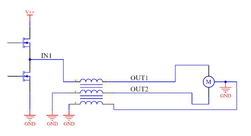
Simply grounding the shield at both sides without the presence of the ferrite bead would provide a path for some of the current coupled from the coils to the stator to return back to the driver. This is a preferred return as the area of the resulting loop (driver ground, to driver, to wire to motor coil, to stator, to shield, to driver ground) is very small as the shield surrounds the driven wires. However, the current divides according to the impedance of both paths, and the chassis commonly as a lower impedance. 

Another way of looking at this is the reverse drop across the shield is “pulling” the current injected by the switching phase charging the winding capacitance back through the shield (as well as the rest of the driver lines). The impedance “toll bridge” of the ferrite bead only applies to one-way currents, not to balanced currents. 

As to circulating currents from the ground loop, these see the bead impedance, and thus are significantly attenuated – the Bead breaks the loop at high frequencies. The optional series capacitor will break the loop at DC and low frequencies if that is an issue in your system.

So, Balun or Shield with Bead?

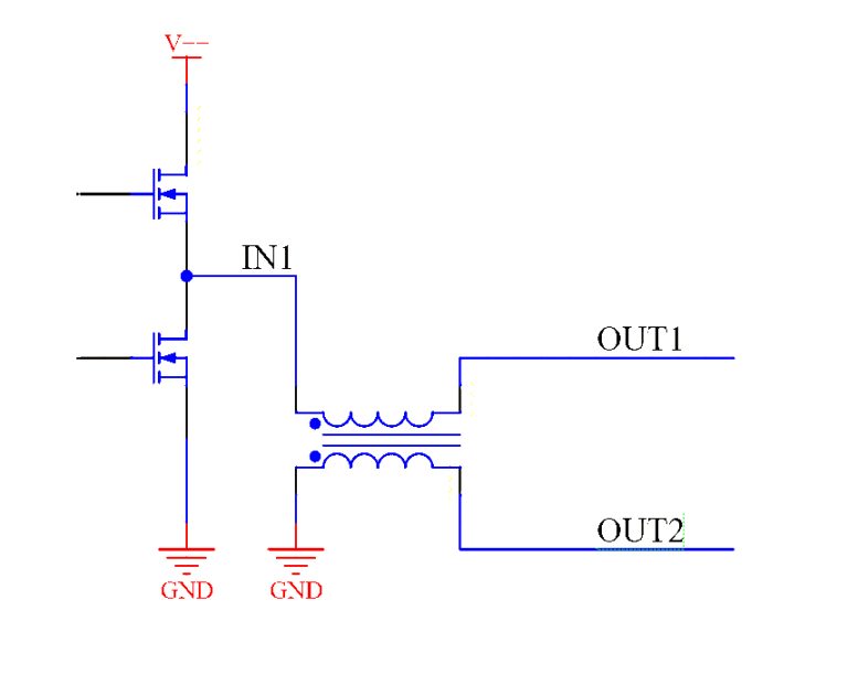
My experience is that if you must choose one, the shield and the bead does more than the Balun alone to reduce noise. However, you are free to choose both. A small through board U and I core close to the drivers but capturing all of the driver lines can make a small but effective balun while still using a shielded cable with a bead to the motor.

What Beads Should I Use?

I have primarily used Type 31 suppression ferrite as well as type 43 suppression ferrite materials from Fair-rite, but there are many ferrite sources. Lossy ferrites are useful in that they convert the noise into heat rather than just reflecting the energy or resonating it. A small amount of heat is vastly preferable to radio emissions or coupling switching noise into other nearby circuits.

QuickSilver Controls uses multiple techniques to reduce noise allowing use of our products in RF sensitive environments as well as in high RF environments such as RF susceptibility test chambers. These techniques also allow QCI to use single cables for both motor signals and encoder signals, tested to 200 feet (61 meters), although we normally suggest shorter runs.

A spring is attached to a servo motor.

Improperly Testing Belt Tension Can Easily Damage Small Motors

Improperly Testing Belt Tension Can Easily Damage Small Motors Interesting Projects Blog July18 2024 | Donald P. Labriola PE Most of us want to just instinctively squeeze a belt between a pair of pulleys to test the belt tension. What is not as instinctive is just how much force such a procedure can put on the shaft — often significantly past the manufacturer’s rated limits for small motors. This can cause damage to both the shaft and the bearings. First

Read More »
Mosolver Cutaway

Servo Motion Actuator Replaces Encoder With Position Sensor

Servo Motion Actuator Replaces Encoder With Position Sensor Interesting Projects Blog July 15 2024 | Donald P. Labriola PE For engineers seeking a motor scaled down in size but not power, QuickSilverControls has extended its Mosolver (portmanteau of “motor” and “resolver”)servo motion actuator into a NEMA 17 frame format. The follow-up to its NEMA23 Mosolver, the goal was to meet the needs of companies operating spacesensitiveequipment.The solution adds a position feedback sensor into the structure of a high pole count

Read More »

The Case of the Noisy Bus Bar

The Case of the Noisy Bus Bar Interesting Projects Blog June 26 2024 | Donald P. Labriola PE We were working on a large medical analyzer that had a computer card cage across the top of the instrument. The power supplies were located in the base of the instrument. The power supplies were located on a slide out “drawer” with flexible access wiring. To minimize voltage drop and packaging size, a formed multi-layer Bus Bar was used to bring the

Read More »

Leave a Reply

Your email address will not be published. Required fields are marked *