Integrated Hybrid Servo Motors Vs Standard Integrated Servo Motors

Interesting Projects Blog
April 10 2025 | Donald P. Labriola PE
Different motor types favor different application areas. No single style has advantages in all application spaces. Direct Drive applications favor Hybrid Servos while high speed geared down applications tend to favor the conventional Servo motors. Misapplication of a conventional servo into a Direct Drive application may result in a 1/3 the efficiency and provide only 40% of the continuous power at a typical application speed. This leads to 160% to 450% more heat being dissipated by the conventional Integrated Servo Motor as compared to a similarly sized NEMA 23 frame (4 inches long) Integrated Hybrid Servo Motor.
Integrated Servo motors fall into a couple of main camps – traditional low pole count AC brushless, and Hybrid Servo which use high pole count AC brushless motors – the latter may also be used open loop as step motors. The Integrated Hybrid Servo motors, as used in this comparison, are operated as true servo motors using vector drives. These comparisons do not hold for step-loss prevention mode step motor drives, even though the same style of motor may be in use. This closed loop versus open loop performance difference is also true of low pole count motors: the same motor performs significantly better when using a full servo control than when the same motor is driven a variable speed drive.
Fundamental Motor Differences
Hybrid Servo Motors are based on High pole count (typically 100 pole) motors typically called step motors when operated open loop. Traditional Servo motors typically use lower pole count (typically 4-16 pole) motors. Given the other motor factors being the same, the torque constant (Nm/A) for a motor increases with the number of poles, and the speed goes down by the same ratio. The torque constant (if losses are accounted separately) equals the voltage constant when expressed as volts/radian/sec. In this example comparison “A” brand integrated servo motor lists the voltage constant as 6.6v/1000 RPM which corresponds to .06 V/Radian/sec which also equals .06 Nm/A, and a winding resistance of 1.1 ohm. The QCI Integrated Hybrid servo has a measured voltage constant of .227 V/Radian/Sec, and a winding resistance of .66 ohms. This means that this conventional servo requires more than 3.5 times as much current to produce the same torque at the shaft as does the Hybrid Servo. Power loss is calculated in the copper windings by Ploss equals I2R. This corresponds to more than 20 times the power dissipated just to hold the same torque when the motors are stopped. Thus a high torque constant is very beneficial at low to medium speeds; however, the high torque constant also causes a higher motor backEMF for a given speed, which reduces the voltage available to the drive current into the motor at higher speeds. This condition limits the top speed of the motor. These differences make the Hybrid Servo motor very useful for many Direct Drive applications, but limits their use in very high speed applications where the lower pole count motor wins out.
Comparing Torque Curves
The torque curves are shown for the two motor types. As you can see, the Hybrid servo has more continuous torque up to approximately 2000 RPM, and more continuous torque than the “A” motor has peak torque up until approximately 1500 RPM. These are important speeds for Direct Drive applications – that is with the motor directly driving the load without a gearhead. A typical lead screw – ¼ inch, 24 inches long, both ends secured with a single bearing, has a critical speed approximately 1600 RPM, while extending the leadscrew to 36 inches drops the critical speed to just over 700 RPM[i]. A typical direct drive belt drive (1” diameter pulley = 3.14”/revolution) moves at 52 inches per second while rotating at 1000 RPM.

Output Power Available
The chart of output power versus speed shows that the Hybrid servo has approximately constant power from 700 RPM up to nearly 1500 RPM, which again nicely covers the Direct Drive requirements. This means that the speed can be chosen within this speed range and will still be fully utilizing the motor capabilities. The Conventional servo data shows power out through 7000 RPM, but has been truncated to fit the graph. While the continuous power of the “A” motor does extend up to 226W at higher speeds, the continuous power at 1000 RPM is just 35W compared to 90W for the QCI-X23C-3 Hybrid Servo. Thus determining the preferred motor type definitely depends upon how the motor is being applied!

Motor Efficiency vs. Speed
The motor efficiency for the QCI Hybrid servo was directly measured, while the efficiency for the Traditional servo was approximated based on the torque and the I2R losses and estimated speed related losses, as well as the input current of 6.6A at 48v producing .33Nm at 6500 RPM (226W out, 318W in, some 92W waste heat). With the continuous torque curve stated as based on an 85C case temperature, the power being dissipated by the motor has been taken as approximately continuous across the speed range for these calculations.

What is readily apparent is that the Hybrid Servo Motor and Controller are significantly more efficient than the Conventional Servo motor up to about 3200 RPM. At 1000 RPM, mid-range for many direct drive applications, the Hybrid servo is some 225% as efficient than the continuous operation of the conventional servo motor, and some 300% as efficient when comparing against the peak torque curve of the conventional low pole count motor (which is still only producing only about 64% of the hybrid servo torque). Again, there is a wide speed range of high efficiency operation for the Hybrid Servo Motor. Note: the curve has been somewhat truncated to show the Direct Drive range of speeds; the “A” system eventually reaches an efficiency of 71% at the “Nominal Continuous power point of 6500 RPM. While this may be useful for applications that actually need this speed, it is not accessible for most Direct Drive applications.
Although both motor types have an efficiency of zero at zero speed, the Hybrid Servo system takes only some 20W to hold a 1.2 Nm load when stopped, compared to an estimated 90W needed to hold the conventional servo at .31 Nm, and an estimated 250W for the peak holding torque of .56Nm when stopped! This difference is very important in gluing fixtures, grippers, vertical loads, clamps, and similar loads which spend a significant portion of their time stopped with torque present.
Typical Direct Drive Applications
Many direct drive applications require motor speed between 250 RPM to 2000 RPM. For example, piston direct displacement pumps for precision delivery are usually in the 250 to 500 RPM range. Belt drives, as shown earlier, are 200-1000 RPM. Lead Screws typically range from 500 to 1500 RPM for a wide range of applications, with the speed is not only limited by the critical speed (first resonance) of the lead screw, but also by the lead nut speed rating, which can often limit the speed of even short lead screws.
So How Are These Hybrid Servos Less Expensive?
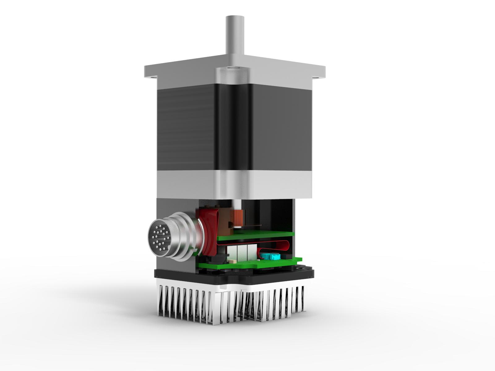
The Motors used for the Hybrid Servos are based on the Step Motors, produced at a rate of many millions of motors per month. The designs use a significantly smaller amount of magnetic materials, and the usually single magnet (with a long 3 stack motor having 3 magnets) is axially aligned with the rotor, making for easy installation which does not require careful alignment and grinding. Although the pole count is high, the single magnet is shared between all of the rotor poles by a clever homopolar design. These motors are also internal permanent magnet motors (IPM), which is a technology just starting to be used for higher end servos and high efficiency motors. The use of the IPM design allows for field weakening methods to be used which allows the peak power and efficiency speed ranges to be extended. The field weakening methods also allow the ultimate motor speed (albeit at a reduced torque) to be extended beyond that which would normally stall the motor due to the backEMF exceeding the drive voltage. Due to the higher pole count, the commutation frequency for these motors is significantly higher than for the low pole count motors, but the speed increase in Digital Signal Processors (DSP) has made this less of a problem.
Summary
The high continuous torque provided by the high pole count motor allows the motor to actually reach its maximum power capability in many Direct Drive applications without needing a gear head to match the motor speed to the application speed. This means you can actually use the rated power at the needed speed. Using a higher speed rated motor in a typical Direct Drive application means buying a 200W motor and driver and then only being able to getting 30W or 40W into your application, or adding a gearhead (which with its added size and cost and reduced reliability, really changes the comparison!). As shown, proper matching of the motor speed characteristics to the load requirements significantly reduces power usage and the resulting wasted heat. This result may be counter intuitive when considering a traditional servo is considered to have high efficiency, but this high efficiency is only available in the narrow range near its optimal operating speed: the efficiency is much lower when operating below that speed. Also remember, for positioning applications, the holding power requirements may actually dominate the total heating!
The Hybrid Servo motor very effectively services a sizable range of Direct Drive applications with lower cost, smaller size, and a higher efficiency than is accessible to conventional servo motors.
Related Posts
Operational Advantages of Integrated Motors
Operational Advantages of Integrated Motors Interesting Projects Blog April 17 2024 | Donald P. Labriola PE Combining a motor with
The Hybrid Servo Motor – Stepping up to Closed Loop
The Hybrid Servo Motor – Stepping up to Closed Loop Interesting Projects Blog October 1 2024 | Donald P. Labriola