New Ideas for Controlling Motors

Interesting Projects Blog
August 28 2024 | Donald P. Labriola PE
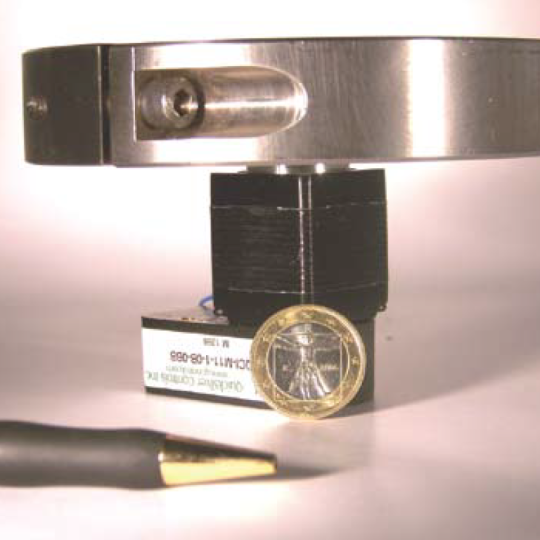
The design of most medical devices is driven by attributes such as size, cost, capability, and reliability. Portable equipment, for example, must work efficiently to provide long battery life. Some equipment must minimize the heat it dissipates to prevent liquid samples from evaporating or degrading. Additionally, the minimal use of wear components such as brushes, gear heads, and bushings helps increase equipment life and reduce maintenance.
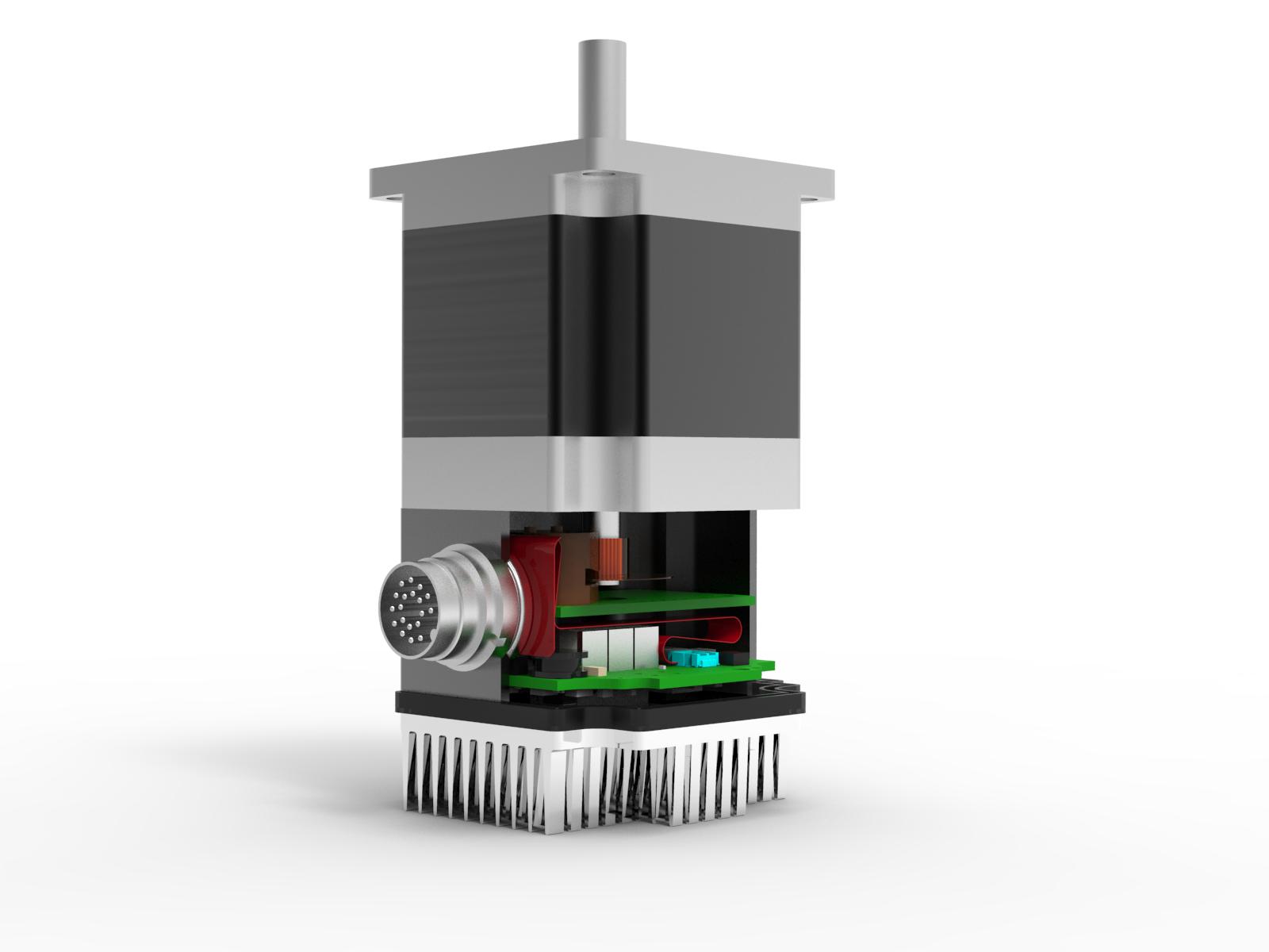
Fortunately, the motion control industry continues advancing to keep up with demands from medical-device manufacturers. For example, the trend to distributed motion control addresses a demand for smaller and more efficient medical equipment by reducing the need for cabling. Such systems also efficiently distribute heat while allowing for effective modular subsystem- level testing.
In other updates, brushless designs have generally replaced brush motors, while servos have replaced many open-loop step-motors. Motion controllers, too, have improved with combinations of rich peripheral sets; fast, general-purpose and numeric processing; and large amounts of onboard memory. In fact, each device generation increases speed by a factor of two to four. In addition to “glue logic” (custom electronic circuitry needed for compatible interfaces between two or more different off-the-shelf components), some DSPs now even include redundant internal clocks. This lowers device cost and size, as well as simplifies the EMI/EMC design by keeping high-speed busses and noise-sensitive nodes inside the chip. The advantage of high-speed busses onchip is to lower radiated EMI and make it less likely that transients from the drive circuitry
might negatively affect the DSP. In addition, an onboard frequency synthesizer reduces EMI radiation from the oscillator circuit. The synthesizers also allow the use of low-cost and durable crystal oscillators. Motion controllers with large amounts of processing power are more flexible than previous units. For instance, controllers now include self-diagnostics and communications protocols such as CANopen, even in the small form factor devices widely used in medical applications.
Motor Selection
Recent controllers with large amounts of processing power provide new options in motor selection. Other factors being the same, the torque density (a measure of the torque generating capability of a motor compared to its size) scales with the number of poles on the motor rotor. However, the commutation speed needed for the motor to run at a given speed also scales up by the same factor. Highfidelity control of the motor-winding current at this higher bandwidth is possible because of the improved DSP capabilities. Also, the high continuous torque available from high pole-count motors can reduce the need for gear-heads in medical equipment, which, in turn, cuts device size and cost while eliminating sources of backlash and wear.
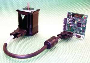
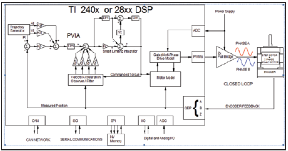
High pole count, two-phase synchronous permanent magnet motors can act as the prime system mover of medical equipment such as pumps, cranes, sample handlers, medicine dispensers, and reaction wheels in blood and fluid analyzers. Such motors are mass-produced for use as hybrid step motors. But they also perform well when operated as if they are ac-PM (permanent magnet) servo motors. An optical incremental encoder mounted to the back of the motor typically provides position feedback. Advanced controllers such as the SilverDust uses position and estimated velocity information as inputs to a software model of the motor state to estimate the motor phase currents. A control loop uses position, estimated velocity, and estimated acceleration to determine the drive commands needed to produce the motor’s motion. The resulting torque command is then fed to the software motor model to determine the required drive voltages.
Operating these hybrid stepper motors as if they were ac brushless PM motors lets them produce up to three times the usable torque and extends operational speeds up to 4,000 rpm. This extends the speed and available acceleration of the hybrids. The closed-loop operation reduces much of the heating often associated with step motors operating in open-loop step mode, as well as eliminates low and mid-frequency resonance issues. Full four-quadrant control and a clamping circuit to dissipate the energy stored in the mechanical system allow for rapid acceleration and deceleration.

While servo control can significantly improve mechanical accuracy and precision, as well as dynamic performance of a system, the small vibration associated with dithering (also known as hunting) in servo systems can increase wear in mechanical components. This is particularly true for mechanisms that spend a significant portion of cycle time at one or more “parked” positions, thereby focusing wear about a small range of motion. The SilverDust solves this problem because it dynamically switches between full servo and open-loop operation when stopped — a feature called Anti-Hunt. When engaged, Anti-Hunt eliminates dithering, which reduces wear and its associated “hum.” Anti-Hunt improves the positioning of microscopes where the continuous motion can cause operator fatigue (and even nausea), operation of pumps where constant motion can cause premature seal failure, and positioning of samples with respect to cameras where vibration causes blurred images.
The controllers work by software-modeling the motor-driver circuit in the DSP to estimate the motor- winding current. The controller uses the model, along with the commanded torque input, to determine the pulse width modulated (PWM) signals required to produce the needed motor shaft torque. This feed-forward current loop compensates for driver cross-over distortion, allows for wide bandwidth in the current loop, and provides high-speed motor commutation.
Consider a typical 1.8º stepper motor with 100 poles or 50 electrical cycles per revolution. Operating these units at 4,000 rpm requires a drive frequency of 3.333 kHz. In contrast, an all-digital drive provides a fast commutation rate and allows using low inductance motors with drive voltages 25 to 50 times higher than the continuous dc voltage rating of the motor. This higher voltage ratio allows for a faster changing of the motor phase currents required for high speed and rapid acceleration.
Movement needed by a system can be commanded either from user programs stored in the controller’s nonvolatile memory or by way of RS232, RS485, or CANopen. The DSP’s trajectory generator calculates position, velocity, acceleration, and optionally jerk, from the requested move, specified in distance/total-time/ramptime move format or distance/velocity/ acceleration move format. The encoder position feedback signal determines feedback position and feeds to a velocity acceleration observer model and filter. The observer model also uses the commanded torque signal to anticipate the reaction of the motor to the drive signal, thus providing an additional servo system phase margin. The additional phase margin reduces overshoot in the system and allows for increased gain and bandwidth for faster movements with less error. The arrangement of the control loop provides smooth transitions from position controlled and velocity limited to torque limited operation without disruptions at transition points. This is useful, for example, when a motion system must switch from positioning mode to constant-torque mode, to limit-gripping force when grasping an object, as well as provide a smooth release switching back to positioning from constant torque while releasing the object. Unlike conventional cascade control loops, the position loop bandwidth need not be degraded for a smooth transition to velocity or torque control. The control loop also allows handling a wide range of load without resorting to gain scheduling. This allows moving a varying load without needing to know the load size ahead of time. The damping made available in the control system allows for large mismatches between the load inertia and the motor inertia — over 100:1. In many cases, this reduces or eliminates the need for gearboxes. To see how controls can compensate for inertial mismatches, visit: quicksilvercontrols.com/SP/DM/Demos. html
Dithering or hunting is a small limit-cycle oscillation — often a couple of encoder counts— characteristic of servo systems. Should a position error happen, the torque command from the controller to the motor gradually builds up to remove the oscillation. But the process repeats because stiction (slip-stick friction) causes the static friction to be greater than the moving friction so the break-away torque needed to overcome the static friction can cause a slight overshoot. But with Anti-Hunt engaged, the controller switches to open-loop operation if an error is sufficiently low, and continues to monitor but not act on the error unless it exceeds a certain threshold. When the threshold is exceeded, the controller switches back to closedloop operation until the error is again sufficiently small to allow open-loop operation.

Related Posts

Operational Advantages of Integrated Motors
Operational Advantages of Integrated Motors Interesting Projects Blog April 17 2024 | Donald P. Labriola PE Combining a motor with

Integrated Hybrid Servo Motors Vs Standard Integrated Servo Motors
Integrated Hybrid Servo Motors Vs Standard Integrated Servo Motors Interesting Projects Blog April 10 2025 | Donald P. Labriola PE
